


Table of Contents
- What is a Tow Hitch and Why is it Needed
- Mechanical Installation: Step-by-Step Guide
- Electrical Connection: A Professional Approach
- Pinout and Wiring Diagrams
Installing and wiring a tow hitch is a technical task that requires precision. Although many car owners attempt to do the installation themselves, faulty wiring can lead not only to incorrect trailer turn signal operation but also to serious problems with the vehicle's own electronics, short circuits, or dangerous situations on the road. This article will help you do everything professionally and safely.

What is a Tow Hitch and Why is it Needed
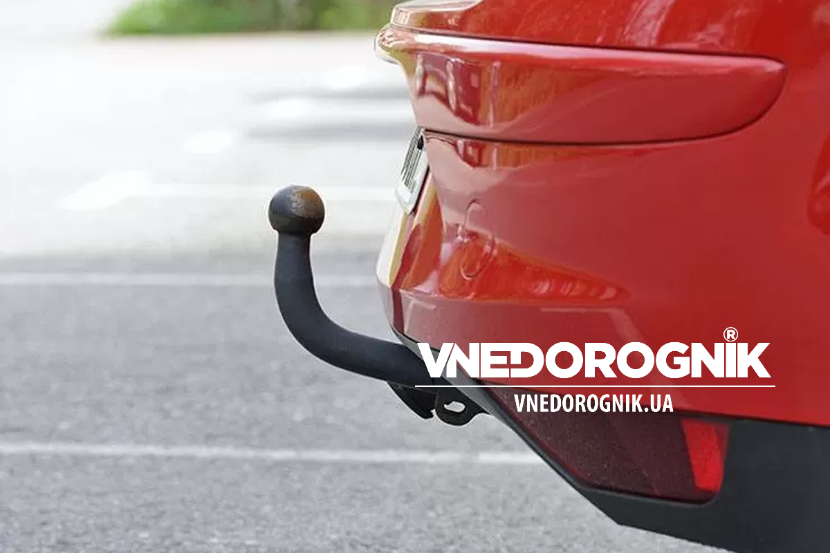
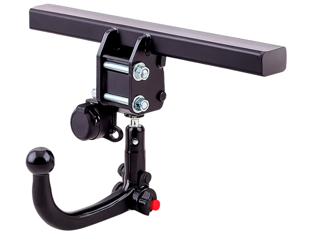
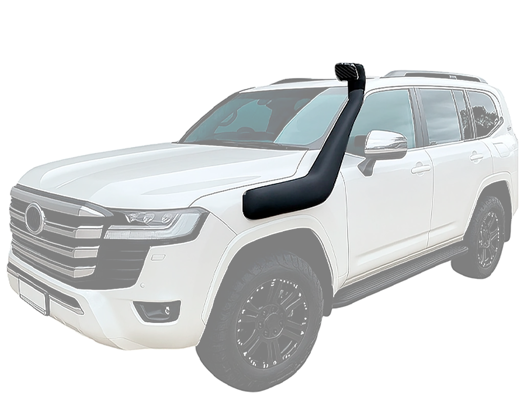
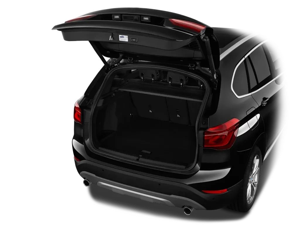
A tow hitch (officially — towing bracket) is an assembly designed for towing trailers, mounting bike racks, or transporting various loads outside the trunk. It is standard equipment for SUVs, crossovers, and is also frequently installed on passenger cars.
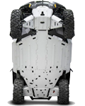
Structurally, a tow hitch is designed individually for each make and model of the vehicle. It consists of two main parts: the crossbar (main beam), which is bolted to the vehicle's frame or body reinforcements, and the tow ball, which is mounted on the crossbar.
Operation: Capabilities and Limitations
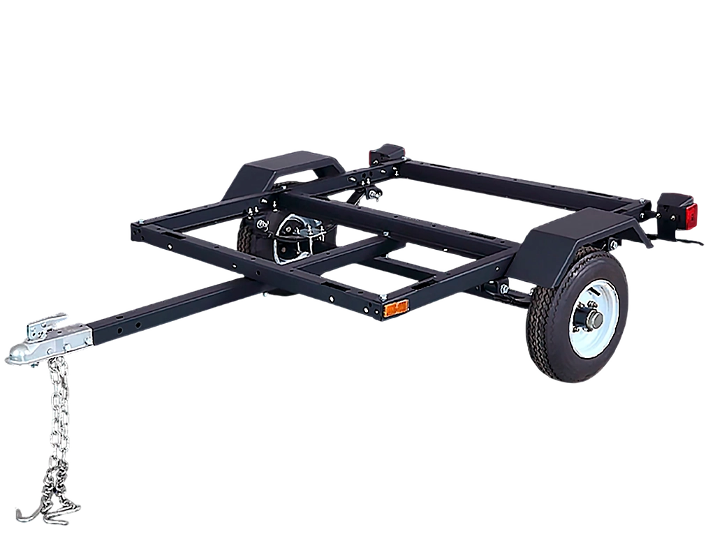
Installing a tow hitch expands the functionality of your vehicle. It becomes indispensable for transporting ATVs, snowmobiles, boats, building materials, or oversized cargo. For travelers, a tow hitch opens up the possibility of towing residential trailers (caravans), turning your SUV into a full-fledged motorhome.
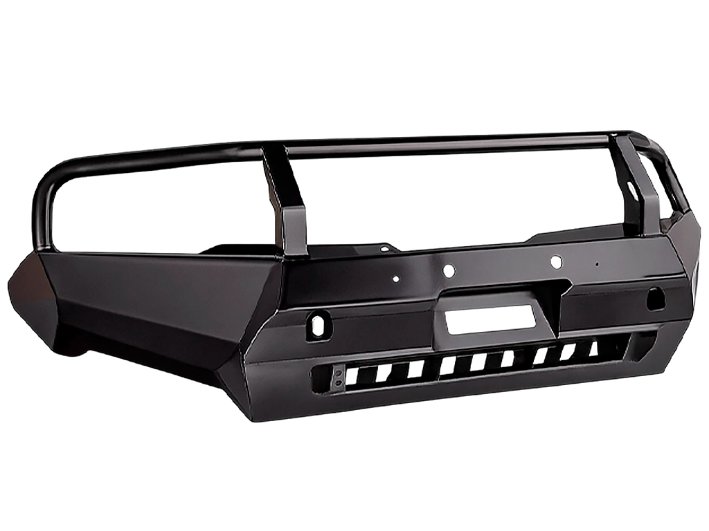
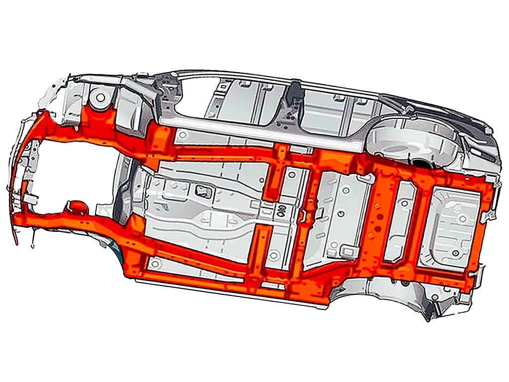
Important: A tow hitch should never be considered a "protective element" for the bumper during an accident. This is a common misconception. In a collision, the towing bracket transfers the impact energy directly to the side members or frame, bypassing the bumper's crumple zones, which often leads to more devastating consequences for the car body than a normal bumper impact.
Mechanical Installation: Step-by-Step Guide
For successful installation, choose a tow hitch that is manufactured specifically for your make and model of car, as there are no universal solutions. A vehicle-specific tow hitch comes with all the necessary mounting holes and hardware for installation.
Required Tools
- Inspection pit, ramp, or vehicle lift;
- Tow hitch assembly (crossbar + ball);
- Set of wrenches and sockets of appropriate sizes;
- Drill and metal drill bits (not always needed, but good to have on hand);
- Screwdrivers;
- Anti-corrosion agent (for treating new mounting holes);
- Pliers;
- Knife, heat shrink tubing, electrical tape;
- Electric soldering iron or professional crimping tools.
Mechanical Assembly Procedure
- Drive the vehicle onto an inspection pit or lift.
- Disconnect the power from the onboard electrical system by removing the negative terminal from the battery.
- Clear the luggage compartment of items and remove the interior trim around the taillights.
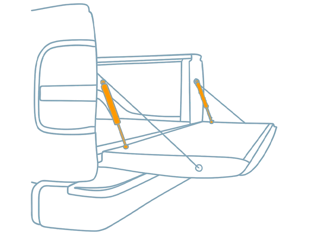
- Often, to mount the crossbar, the rear bumper must be removed as it will obstruct the work.
- Align the crossbar to the mounting points and verify that the holes line up.
- If the instructions require additional holes, drill them and be sure to treat them with an anti-corrosion agent.
- Secure the crossbar using nuts, bolts, and the correct size wrenches, strictly observing the tightening torque specified by the manufacturer.
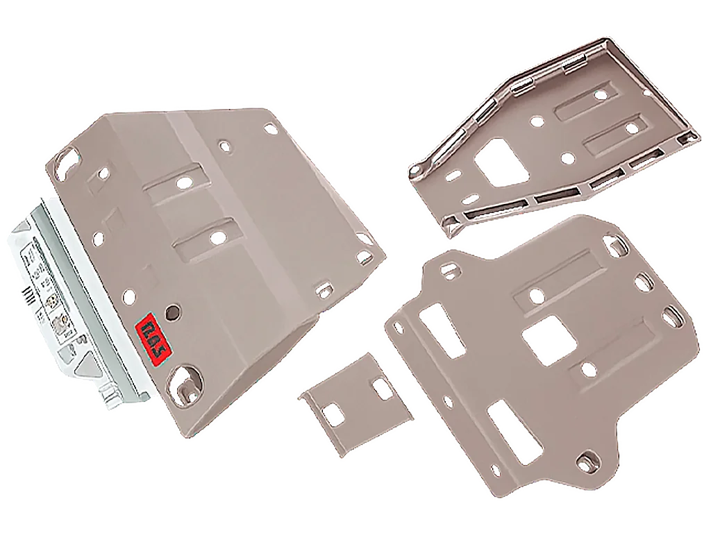
- It is also necessary to balance the load on the vehicle frame to ensure a secure mount. Drill a few holes inside the trunk and underneath, and treat with an anti-corrosion agent. Next, add and secure reinforcement plates and tighten all bolts with a wrench.
Electrical Connection: A Professional Approach
Most manufacturers supply tow hitch kits with a complete electrical set, but sometimes you have to purchase everything separately. An electronic connection kit includes:
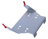
- Mounting plate;
- Special 7-pin or 13-pin socket;
- Set of necessary installation hardware;
- Wiring diagram.
Since the onboard network was depowered in the previous step, you can now proceed directly with the electrical setup. You need to connect the wiring harness to the socket and do everything according to the provided diagram. The socket is bolted to the bracket and connected to the main vehicle wiring.
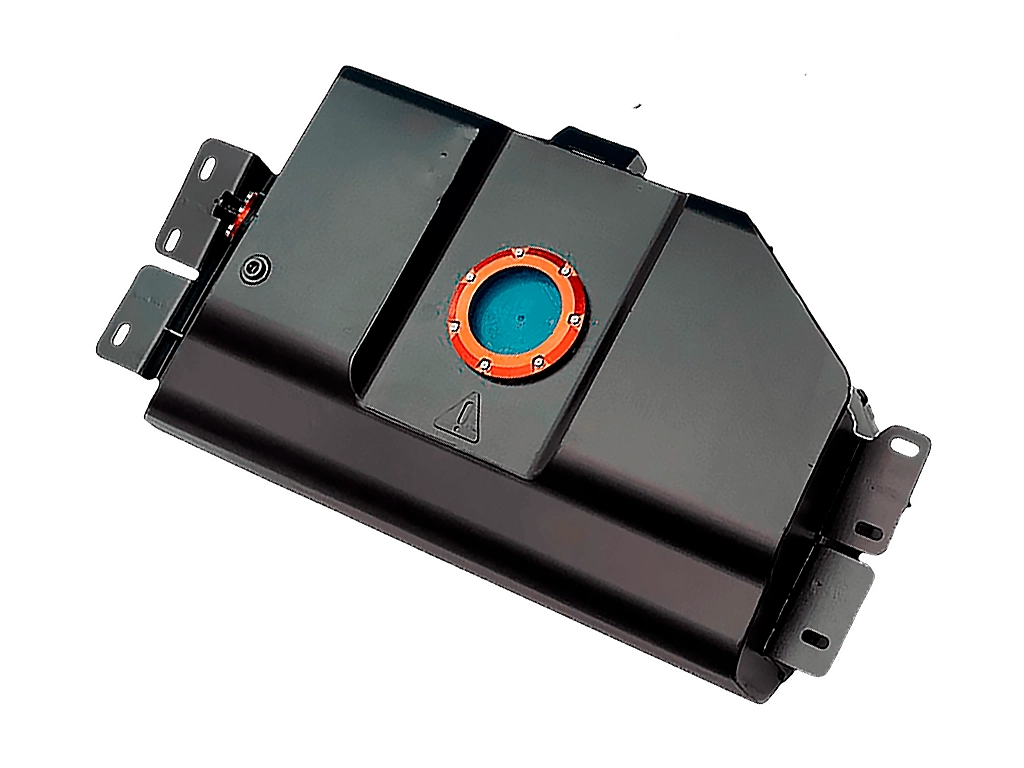
Bypass Relay (Smart Box) – Why it is Necessary
This is a critically important step that is often skipped. Many modern cars (roughly from 2005 onwards) use a CAN bus, multiplexed wiring, and bulb failure monitoring systems. If you simply "splice" into the factory wires, the vehicle's ECU will detect a change in resistance or unauthorized load, which will result in a short circuit, taillights going into safe mode, or even failure of the comfort control module.
A Bypass Relay (or "Smart Box") is an electronic module that connects to the factory wiring ONLY as a signal device. IT DOES NOT DRAW POWER from the taillight circuit. Instead, it takes the signal and uses a separate power feed directly from the battery to supply voltage to the trailer socket. This completely isolates the vehicle's electrical system from the trailer's. Always use a Smart Box for cars with bulb failure monitoring systems!
 Wiring Diagram")
Pinout and Wiring Diagrams
Use the designated hole in the trunk floor to route the socket wiring. If it is not provided from the factory, drill a hole yourself, treat the edges, and use a rubber grommet. Then, make the connections according to the selected diagram.
Socket Types: 7-pin vs 13-pin
As is well known, two types of sockets are used, which differ accordingly by the number of pins and the required connections.
7-Pin Socket Pinout (Standard UA/EU)

This is the most widely used type in Ukraine and Europe, as it is quite easy to wire. It is primarily used in domestic vehicles and only for essential lighting, responsible strictly for light signaling.
- Left turn signal.
- Positive power supply / Rear fog light.
- Earth (Negative connection).
- Right turn signal.
- Right tail light and number plate light.
- Brake lights (Stop).
- Left tail light.
13-Pin Socket Pinout (Extended Functionality)

These sockets are used mostly for American cars or European caravans. This is because trailers (motorhomes) are often used instead of regular utility trailers. They require more pins: for fog lights, reverse lights, and also to provide permanent and switched power to devices inside the caravan (e.g., a refrigerator).
- Left turn signal and hazard warning.
- Rear fog light.
- Earth (Negative connection) for pins 1-8 (35A).
- Right turn signal.
- Right tail light and number plate light.
- Brake lights (Stop).
- Left tail light.
- Reverse light.
- Permanent positive power supply (+12V).
- Switched power supply (+12V from ignition).
- Earth (Negative connection) for pin 10 (35A).
- Spare / Unallocated.
- Earth (Negative connection) for pin 9 (35A).
Testing and Insulation: Always test all connections with a multimeter or test lamp before reconnecting the battery. To protect the wires, use high-quality electrical tape, heat shrink, and, if necessary, sealants. The wires should be secured along the trunk walls, after which the interior trim can be reinstalled.
Looking for reliable towing equipment for your SUV or passenger car? On Vnedorognik.ua you can buy a tow hitch designed specifically for your vehicle model, as well as all the necessary electronics for a safe connection. Trust your vehicle only to high-quality components — order reliable parts and travel safely with your trailer!